Android AMP on i.MX7 ULP
Android 8 Asymmetric Multiprocessing on NXP i.MX7ULP
Introduction
This technical note adds new platform specific contents to the work Kynetics has been doing on the heterogeneous platforms. Refers to the other technical notes as reported in the References at the bottom of this article.
Kynetics has been working on the new NXP i.MX7ULP Development Platform (i.MX7ULP-EVK) still in preproduction. i.MX7ULP introduces interesting new features, like separate not available previously on the the i.MX7 Family of processors, like booting modes, which makes this platform very suitable for portable devices. In particular the Development Kit features Acc, Mag (FXOS8700CQ) and Gyro (FXAS21002CQ) sensors which make possible to implement one of the great use case for heterogeneous platforms: application domain segregation. In this context we may have an application running inside a rich OS (typically for data presentation) and a critical task running on a realtime environment.
Because Android is a very popular OS for rich UIs and its platform internals is one of Kynetics’ primary area of expertise, we have developed a case of study where an Android application displays sensor data acquired from the M4 core.
For this and other heterogeneous applications we have developed some Android OS customizations that we call Android Cohesys to emphasize the collaboration/cohesion between MPU and MCU from a software standpoint.
System Features
In the overall application, the workload is distributed across the cores: the MCU (running FreeRTOS) takes samples from the IMU board (i2C) and periodically sends data to the Android OS (Oreo) running on the MPU over a RPMsg channel. Accelerometer, gyroscope and magnetometer data are then plotted by an Android App. The Android App nicely shows also dome statistics about the tasks running on the micro-controller.
A very similar application has been implemented for the Toradex Colibri i.MX7D SOM and for the Boundary Devices Nitrogen 7 single board computer. Refer to the specific technical notes for details.
With the latest software package for i.MX7ULP, NXP introduces some radical improvements in the structure of FreeRTOS multicore software. These changes will be discussed in this note.
What's new on i.MX7ULP
The i.MX7ULP SoC is explicitly targeted at low-power portable devices, such as wearables, IOT edge solutions and portable patient monitoring devices. A diagram of the i.MX7ULP architecture is shown below:
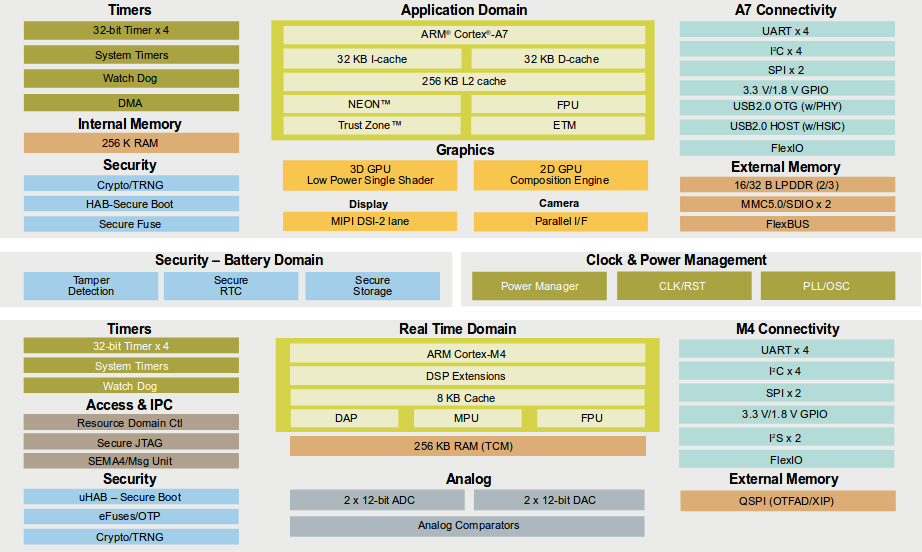
Differently from all other heterogeneous platforms of the iMX family, where the microprocessor (Cortex-A*) is the main core and the micro-controller (Cortex-M*) is the auxiliary core, the i.MX7ULP platform supports two more boot modes, allowing to swap primary/auxiliary roles accordingly to the power saving profile needed for te specific use case.
The supported boot modes are:
- Dual Boot: M4 is the primary core, A7 is the auxiliary core. M4 loads from QSPI and boots A7 from eMMC/SD. This is the default boot mode for i.MX7ULP.
- Low Power: M4 is the primary core, A7 is the auxiliary core. M4 loads from QSPI and boots A7 on demand.
- Single Boot: A7 is the primary core, M4 is the auxiliary core. A7 loads from eMMC/SD and boots M4.
In particular Quad Serial Peripheral Interface (QSPI) is a SPI module that allows single, dual and quad read access to external SPI devices.
One of the disadvantages of the i.MX7 was that the MPU was always the primary core. In other words there is no way for system to boot the A7 core by the M4 core. For this application we chose the Dual Boot mode; the M4 always starts first from QSPI and brings up the A7 core running Android. Power management of the A7 core (suspend/resume/reboot) is entirely handled by the M4 core.
MCUXpresso SDK
The MCUXpresso Software Development Kit provides software source code for the i.MX7 ULP M4 core including peripheral drivers, RTOS kernels, device stack and other middleware, to support rapid development on this platform. The SDK includes also a rich set of demo applications, that can be used standalone or in conjunction with the A7 core in a multi-core configuration. You can get the specific SDK by using the SDK Builder and specifying i.MX7ULP-EVK as the target development board.
The SDK provides a sort of middleware which includes RPMsg Lite as the transport for multicore configurations, which is a lightweight implementation of the RPMsg protocol targeted at small micro-controllers. Compared to the OpenAMP implementation, RPMsg Lite has a smaller footprint and improved modularity.
Multicore examples are located in the <SDK_ROOT>/boards/evkmcimx7ulp/multicore_examples subfolder, including also a pingpong application as an example of usage of RPMsg Lite APIs.
The SRTM services
With M4 now being able to act as the primary core, management of power rails and peripherals such as audio, I/O, RTC and sensors can be shifted from the microprocessor domain to the microcontroller domain. The A7 core can access resources indirectly by communicating with the M4 core, which handles the hardware peripherals.
From a software standpoint all of these peripherals has been arranged in the form of services. Each service implements access to its hardware peripheral and handles communication towards the A7 core. For each resource in the micro-controller domain, there is a counterpart device driver on the Android kernel which handles communication with the primary core (M4 in our case) and exports the required resources to the Android userspace. Communication between the cores is carried out using the RPMsg protocol.
The following services have been implemented by NXP and source code is available in the SDK examples srtm/services/ subdirectory.
-
SRTM Audio Service: handles audio playing - Android kernel counterpart:
sound/soc/fsl/fsl_rpmsg_i2s.c -
SRTM I/O Service: handles GPIO pins - Android kernel counterpart:
drivers/gpio/gpio-imx-rpmsg.c -
SRTM Keypad Service: handles the keyboard - Android kernel counterpart:
drivers/input/keyboard/rpmsg-keys.c -
SRTM LFCL Service: handles A7 lifecycle (i.e. suspend/wakeup) - Android kernel counterpart:
arch/arm/mach-imx/pm-rpmsg.c -
SRTM PMIC Service: handles PMIC - Android kernel counterpart:
drivers/regulator/pf1550-regulator-rpmsg.c -
SRTM RTC Service: handles RTC - Android kernel counterpart:
drivers/rtc/rtc-imx-rpmsg.c -
SRTM Sensor Service: handles pedometer - Android kernel counterpart:
drivers/input/misc/rpmsg_input.c
Each service initializes its dedicated RPMSg channel, by which control messages and data are exchanged between the cores. At boot, service announcement messages are sent from the M4 to the A7 and the respective RPMsg channels are created.
Here's the Android kernel output, notifying the creation of the channels:
[    0.638498] pm_rpmsg virtio0.rpmsg-life-cycle-channel.-1.3: new channel: 0x400 -> 0x3!
[    0.701554] gpio_rpmsg virtio0.rpmsg-io-channel.-1.5: new channel: 0x401 -> 0x5!
[    0.858529] regulator_rpmsg virtio0.rpmsg-regulator-channel.-1.1: new channel: 0x402 -> 0x1!
[    2.064863] key_rpmsg virtio0.rpmsg-keypad-channel.-1.4: new channel: 0x403 -> 0x4!
[    2.389428] input_rpmsg virtio0.rpmsg-sensor-channel.-1.7: new channel: 0x404 -> 0x7!
[    2.403621] rtc_rpmsg virtio0.rpmsg-rtc-channel.-1.6: new channel: 0x405 -> 0x6!
[    2.805286] i2s_rpmsg virtio0.rpmsg-audio-channel.-1.2: new channel: 0x406 -> 0x2!
The Sensor Stack
The application discussed in this technical note involves on board sensors and requires full comprehension of the whole Android sensor stack (A7 domain), from the hardware up to the application level. The image below represents the Android sensor stack (not different from other platform implementation) and highlights the two core domains on i.MX7ULP. Control flows from the Android application on the A7 domain down to the sensors on the M4 domain, and data flows from the sensors up to the applications.
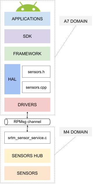
The main components of the stack will be briefly discussed below, starting from the sensor service implementation.
Sensor service (M4 domain)
As we said in the introduction the i.MX7ULP Evaluation Kit comes with different sensors:
- FXOS8700CQ: Accel+Mag
- FXAS21002CQ: Gyro
- MPL3115A2: Pressure
- FXLS8952CWR1: Accel
By default, the sensor service uses the FXOS8700 accelerometer sensor on the board to act as a pedometer, both detecting and counting steps.
Data is collected and sent to the A7 core when needed through the dedicated RPMsg channel. There are three types of messages that the A7 core can send through the channel, each corresponding to a different action:
- SRTM_SENSOR_CMD_ENABLE_STATE_DETECTOR: enables/disables step detector. When the step detector is enabled, the sensor service notifies the A7 core everytime a step is detected.
- SRTM_SENSOR_CMD_ENABLE_DATA_REPORT: enables/disables step counter. When the step counter is enabled, the sensor service periodically sends a message with the current number of steps detected.
- SRTM_SENSOR_CMD_SET_POLL_DELAY: configures the frequency at which step notifications are sent (in milliseconds).
Input driver (A7 domain)
On the A7 side, the rpmsg_input driver in the Android kernel communicates with the sensor service through the RPMsg sensor channel. Once the pedometer has been configured with one of the messages described above, the Kernel driver listens for incoming messages in the sensor channel and exports data to the upper Android layers.
On the A7 side, sensors are represented as standard input devices. Input events are generated by the devices when new data is available.
Sensor HAL (A7 domain)
From the userspace perspective, Android sensors are virtual devices that provide data from a set of physical sensors. In general all sensors drivers provided by manufacturers must implement the HAL interface; this interface is the glue between the kernel or userspace driver and the Android SDK. In some HAL implementations sensors chips may be grouped together as a sensor hub, like in our case.
Going back to our case, events coming from input devices representing our sensors (or the input device representing the hub, if present), carry the sensor payload. These events are handled by the HAL sensor module (which implements the HAL interface) and then the Android Sensor Service which serves the Android API through the Binder. In particular the HAL interface provide a data structure for sensor eventssensor events and interpretation of the input payload depends on the type of the sensor.
The HAL sensor module used in the Android build for i.MX7ULP is provided by the library libsensors_sensorhub. However in the in the NXP code for i.MX7ULP, the it only supports step counter and step detector devices.
Kynetics extended the sensor list to include out target accelerometer, magnetometer, gyroscope.
Android App (A7 domain)
The Android application is the latest layer in the stack and it can easily access sensor data (using the SDK) by registering a listener for a certain sensor's type events. Here's an example of how to get events from an accelerometer with standard SDK calls:
SensorManager sensorManager = (SensorManager) getSystemService(Context.SENSOR_SERVICE);
Sensor accelerometer = sensorManager.getDefaultSensor(Sensor.TYPE_ACCELEROMETER);
sensorManager.registerListener(this, accelerometer , SensorManager.SENSOR_DELAY_NORMAL);
Implementation Details
Here we'll briefly describe the steps taken at each layer to of the sensor stack from the bottom to the top.
Sensor service (M4 domain)
The NXP default implementation of the sensor service has been modified in order to use all three sensors as separate inputs: accelerometer, magnetometer and gyroscope as an IMU device (Inertial Measurement Unit) instead of using only the accelerometer to detect and count steps (i.e. pedometer).
Command messages have been edited as follows:
- SRTM_SENSOR_CMD_ENABLE_DATA_REPORT: enables/disables IMU device. When IMU is enabled, the sensor service periodically sends a message with the current values from accelerometer, magnetometer and gyroscope sensors.
- SRTM_SENSOR_CMD_SET_POLL_DELAY: configures the frequency at which IMU data notifications are sent (in milliseconds).
Once the IMU device has been enabled and the poll delay has been set, the sensor service starts to periodically send IMU data to the A7 core. All messages are exchanged on the RPMsg sensor channel.
Input driver (A7 domain)
On the A7 side, the RPMsg input driver creates three misc devices, each representing each IMU sensor:
static struct miscdevice accel_device = {
    .minor = MISC_DYNAMIC_MINOR,
    .name = "FreescaleAccelerometer",
    .fops = &rpmsg_input_fops,
};

static struct miscdevice mag_device = {
    .minor = MISC_DYNAMIC_MINOR,
    .name = "FreescaleMagnetometer",
    .fops = &rpmsg_input_fops,
};

static struct miscdevice gyr_device = {
    .minor = MISC_DYNAMIC_MINOR,
    .name = "FreescaleGyroscope",
    .fops = &rpmsg_input_fops,
};
Each of these misc devices has two sysfs attributes that can be used by the upper layers to enable and configure the IMU device:
- enable: used to enable/disable the IMU - send SRTM_SENSOR_CMD_ENABLE_DATA_REPORT message to M4
- poll_delay: used to set the poll frequency (in ms) - send SRTM_SENSOR_CMD_SET_POLL_DELAY message to M4
The driver also registers one input device, representing the sensor hub.
When IMU data arrives on the sensor channel, the driver parses the data and generates the events for the three sensors. All events are reported by the sensor hub input device.
Here's the output of the Android getevent command, that shows input events coming from the sensor hub device:
evk_7ulp:/ # getevent -l
add device 4: /dev/input/event4
  name:     "SENS_HUB"
/dev/input/event4: EV_REL       REL_X                00000070       /* ACC X event */
/dev/input/event4: EV_REL       REL_Y                00000040       /* ACC Y event */
/dev/input/event4: EV_REL       REL_Z                00003f10       /* ACC Z event */
/dev/input/event4: EV_SYN       SYN_REPORT           00000000
/dev/input/event4: EV_REL       REL_RX               0000008b       /* MAG X event */
/dev/input/event4: EV_REL       REL_RY               00000292       /* MAG Y event */
/dev/input/event4: EV_REL       REL_RZ               000000f7       /* MAG Z event */
/dev/input/event4: EV_SYN       SYN_REPORT           00000000
/dev/input/event4: EV_REL       000a                 00000258       /* GYR X event */
/dev/input/event4: EV_REL       000b                 fffffce0       /* GYR Y event */
/dev/input/event4: EV_REL       000c                 000002bc       /* GYR Z event */
Sensor HAL (A7 domain)
The sensor HAL has been modified to disable the step counter and step detector devices and enable the other sensors on board sensors.
The libsensors_sensorhub implements the HAL interface for events coming from the sensor hub input device.
Note: in our Android Cohesys build the NXP proprietary sensor fusion library fsl_sensor_fusion has been disabled.
Application (A7 domain)
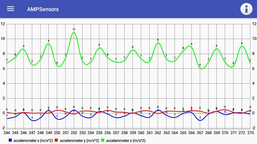
An Android application has been developed to visually plot the sensor data. The application registers an event listener for each sensor. Data is then plotted on individual graphs; each graph shows the three x, y, z components of the each sensor.
The images below shows the plot of the accelerometer while moving the board:
MCU Statistics
We wanted the M4 to also periodically send statistics about the tasks running on FreeRTOS. Data such as name of the task, current status and MCU usage are gathered by a Statistics Task and sent to the A7 on a dedicated RPMsg channel.
Statistics are plotted nicely on the Android application, to peek on the current micro-controller's load:
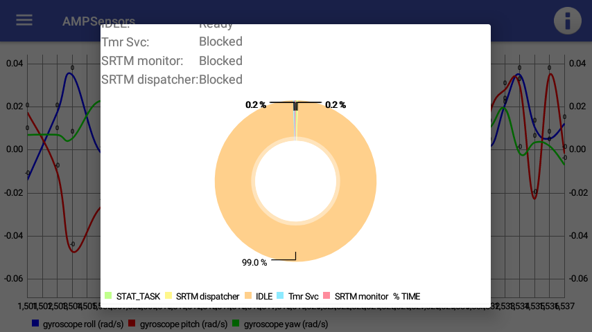
As shown in the image, the MCU is IDLE most of the time.